
My own DCC control station and a new engine
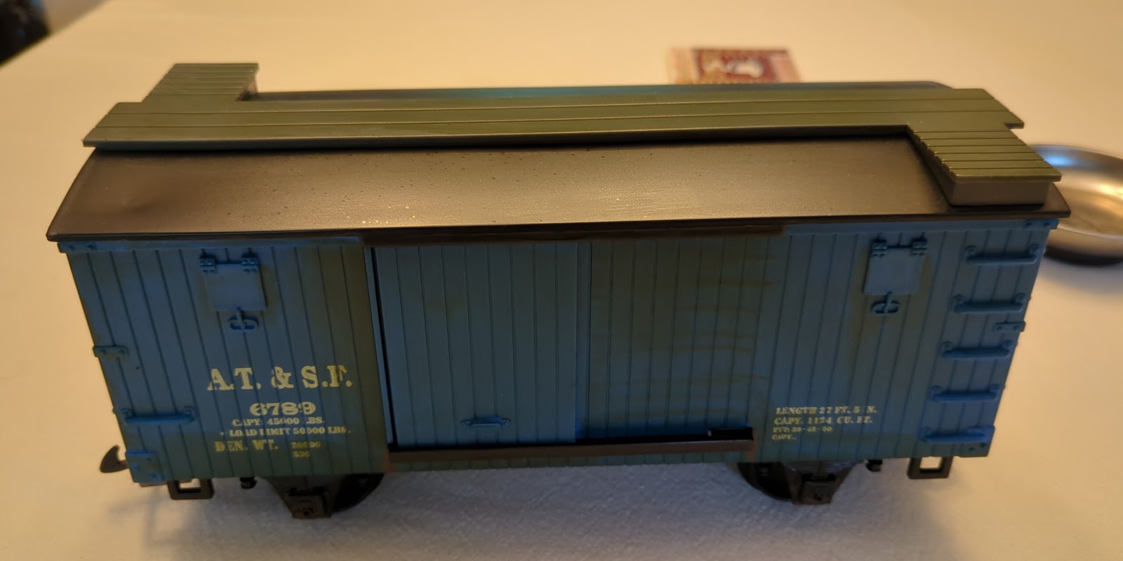
As discussed in my recent Santa Transport post, I received a new LGB engine for Christmas. The Christmas point-to-point set up runs on DC power so I can control it directly with an Arduino. It is nice that the engine plays sounds during DC operations but the real glory is all the capabilities available via DCC. This weekend I finally had the chance to set up a DCC test track for the engine.
 |
| Arduino Mega, Motor Driver Shield, wifi Shield, and power supply for DCC EX |
I found I had not made good notes previously but remembered I had the software installed but ran into trouble getting it to control anything. When I got it back out it kind of worked when connected to the computer but I wasn't getting the expected responses over wifi.
I put the DCC EX aside and brought my outdoor DCC controller inside so I could at least test the new engine. Choo-choo! that worked great with no tweaking. I was able to test out the sounds and reporogrammed the engine number. It is interesting that things like the bell and whistles aren't at the same default function buttons as my TCS decoder. Or even the labeled buttons on Engine Driver on my phone; maybe it's a European vs America thing? After adjusting the volume, it was really loud for indoors, I ran the train back and forth a few times.
Returning back to the DCC EX station, I saw I had missed connecting up a couple of jumper wires between the Arduino and the wifi shield when I got it out of storage. Thinking that was the problem, I wired those up. And no joy. Must be something else.
But something was nagging at me. I needed to connect transmit (Tx) and receive (Rx) on the wifi shield to Tx/Rx #1 on the Arduino Mega board. But the shield was already connecting them to Tx/Rx #0 through the stacked pins. Maybe those pins shouldn't be connected down through the stack? But how to test? I thought about wrapping the pins in electrical tape but the tape was going to be too long and too think to fit in the header below. There had to be something else to protect those pins from connecting. But no ideas were coming to me.
And then it hit me while doing something else, the wifi shield just needs power and the Tx/Rx connection to the Arduino; it doesn't really have to be stacked with the other boards. So I attached a few jumper wires and laid it off on the side. It was attached but not through the header pins. Everything worked as expected! A quick trip to the garage to clip the pins off for Tx/Rx on the wifi shield and then I could stack the shield back on top.
For the controller I installed Engine Driver on an old phone.
 |
| Layout with DCC EX stack and Engine Driver |
Interesting look at the workings ‘behind the curtain’.
ReplyDelete