How far do we go?
For a while, I've been wanting to try and combine my nascent interest in electronics with the railroad development. As I've said before, I was never really a hands-on tinkerer growing up but there is something really satisfying with ending up with something that you designed and constructed. I've always been a "designer" but seldom took my ideas to realization until the last several years. Both model railroading and electronics are outlets for taking that next step. Being able to modify some part of the train and do something that it couldn't have done before was an intriguing challenge. I've only started with electronics a couple of years ago when I my wife gave me a SparkFun Inventor Kit. The kit comes with a RedBoard which is their version of an Arduino Uno and comes with a many sensors, motors, and other electronics. Plus a book full of fun projects to learn from.
A few years ago I was inspired by an article in Garden Railways magazine by Del Tapparo for an Arduino-based odometer. I could have just implemented what he did but I wanted the experience of designing and building it myself. The basic design is to use a reed switch under the floor of the car that would detect a magnet attached to the inside of one of the wheels. The Arduino would count the number of times the reed switch closed, tally that up, and then display the count, or a distance. I built the first version using mostly pieces from the Inventor's Kit plus a reed switch and magnet.
 |
| Wiring diagram |
In previous experiments with the reed switch I found that it was really susceptible to bounce - where it would switch open and closed several times when the magnet passed by. This is a common challenge with mechanical switches and there are several approaches to manage this, also called debouncing. I am going with the simplest approach
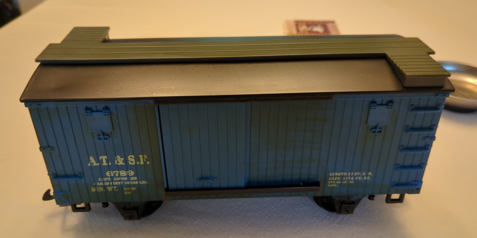
I also need to figure out which car to use and how to install the circuit. I have a refrigerated car that came with the train starter kit that doesn't really fit my theme right now. I use this car as a convertor between coupler types so it's a utility player already and as good an option as any for playing around with. But how to open the car up? Hmm, the doors don't slide; there's no giant entrance sign. Well, the roof does lift up a bit so with a small screwdriver, I'm able to pry it off. Since the tabs are attached to the roof, I pull the side of the car out slightly and the tab releases. BINGO! the roof is off and there is plenty of space inside for all of the electronics, even in this prototyping stage.
 |
| Refrigerated car I plan to use for this build |
 |
| Raising the roof! |
It is unfortunate that the doors don't open as that would've been a good place for the display. Maybe a future experiment in modification?
As I'm designing the system I want to test the reed switch so I set up a simple circuit that would light an LED when the switch was closed. I simply ran power through the switch and then to a resistor and on to the LED. I used the Arduino board for power since I don't have a simple way to feed power to the breadboard but no programming was involved. You can see the light flashing in the following video. This simple circuit also lets me test where to mount the reed switch.
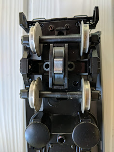
When I first placed the magnet on the wheel it immediately jumps to the axle. Turns out the metal wheel itself isn't magnetic but the axle is. Not ideal but for now having the magnet on the axle is good enough as the magnet is strong enough trigger the reed switch. I put the truck back on the car and move the reed switch around to find the best location for robust operation no matter how the trucks turn. Two small holes through the floor and I can attach the reed switch. Putting the Arduino, the breadboard with the circuit, and the battery pack inside the car completes installation.
 |
| Circuit ready to insert into the car |
Now I focus on programming the Arduino. The design is straight-forward since all it needs to do is monitor for the switch to trigger, increase the counter when it is detected, convert the count to a distance, and display the distance on the LCD screen. The LCD has a standard library so I just need to call the print function to write to it. So that no triggers are missed, I attach the reed switch to one of the Arduino's built-in interrupt pin. The Arduino monitors the pin and interrupts the program whenever a signal comes it. It jumps to a function I specify and then returns to the normal control of the program.
At regular intervals-- I chose half a second to start-- the distance is updated on the LCD screen. I also added a push button to reset the odometer. The button is checked in the main loop and if pressed, the program resets the counter. I also wanted to get a sense of the speed of the car. At the first reed switch trigger after a reset, I record the time. Then, whenever updating the LCD screen, the average speed is calculated by dividing the distance by the time since the car started. As a potential improvement, I might change that to just monitoring the last 5 or 10 cycles and doing the speed calculation over that time for a more "instantaneous" speed.
I was working on this over the Christmas holidays so I had a test track under the tree readily at hand. A quick run around the track looked good. The distance was going up and it seemed reasonably close to my quick calculation of what the track distance should be.
 |
| After a few trips around the Christmas tree |
To do the conversion from cycles to distance I guess at the radius of the wheel and convert that to a circumference. It looks close but I want to do a more accurate calibration. Del Taparro's version actually has a calibration function built-in but since I'm not planning on moving the circuit from car to car, I plan to hardcode it. My layout has a nice straight stretch which makes measuring out a known distance easy so I head out there to calibrate. This was also a good time to glue the magnet to where I wanted it on the outer edge on the back of the wheel.
I mark off two spots 10 feet apart and push to car by hand from one to the other mark. Since there is a little variation in where the magnet is when I start and finish, I'll repeat a few times and then take the average number of cycles for the calibration. But the second pass is a couple of cycles shorter. Third pass has yet another value and they differ by two or three cycles. Way more than just a little variation in starting alignment. A few more runs and more different values. What's up?
It's obvious when I turn the car over. The magnet broke away from the glue and is stuck on the axle again. By hand-turning the wheels I see an occasional missed cycle but even more I'm seeing double or triple counts. Being that far from the reed switch means there is an extended time when it is "within range" but always at the outer limit of the range so not too surprising.
And that's where I'm at today. It mostly works but I still need to find a good way to glue the magnet on. That was harder than I initially thought since the pull towards the axle is so much that I struggled to hold it in place long enough for the glue to set. I need to try again and really make sure it is sticking. Maybe a small clamp while the glue dries? I'll see.
Before making everything permanent I would like to change out a few of the components. Using an OLED display instead of the LED would give a nicer display and simplify the wiring. I would also like to move the circuit from a breadboard to a prototyping board. And finally maybe get an Arduino Nano that could permanently stay in the car.


Comments
Post a Comment