How far have we come?
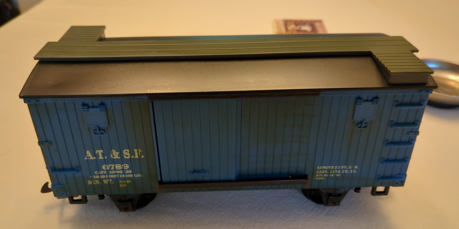
This is part 2 of How Far Do We Go from a few months ago. I left off there with a working prototype of an Arduino-based odometer installed in my refrigerator car. That car was part of a starter kit and doesn't fit well with my theme right now so it is doing duty as a utility and testing car. It was the first car where I replaced the default hook-and-loop coupler with a knuckler coupler. It now is the transition between the starter set and a few of cars I have acquired that came with knuckle couplers. However, as I ended the previous post, that car didn't lend itself very well to having a display or a battery pack with easy access. So I've torn that all out and started with a fresh design.
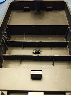
The new design would have a four-line LED display, instead of two-line, to show more data and I decided to have a dedicated Arduino board. After trying a few combinations, I realized that the coal tender would be a perfect place for the odometer. It has a removable coal load with a pocket under which was designed to hold a large battery pack. The display fits wonderfully in that space after trimming down the battery separator walls. There is also space inside the tender where the original sound card was for the Arduino and the extra circuit board I needed. There is even a small battery compartment on top that takes AAA batteries that includes an on-off switch.
 |
| Compartment after I trimmed off tabs in the middle and along the sides |
I committed to the new plan and started modifying the coal tender. There would be just enough space for the display if I trimmed off tabs that stuck up in the middle plus evened up the sides. But first I needed the right, or at least not the wrong, tools. I'm not the most patient modeler so tried a cutting wheel on my Dremel. Go for the quick and easy first. But that was a bit too fast and melted the plastic leaving a very rough edge. So I turned to some files and small saws I have added to my tool collection. This was slower but cleaner. I learned to cut slowly and then take time to file to get the edges that I wanted. What in my mind was going to be a handful of cuts and 30 minutes of work took a few hours but I think I developed an acceptable technique to cut things out. It isn't pretty but also not embarrassingly rough for my first mod. And the good news, it is hidden from view most of the time.
Once the major renovations were done to house the display, I turned my attentions to the electronics design. The display and the Arduino board support QWIIC connections, so connecting the display would be as simple as running the cable from the board to the display. I also needed to detect the reed switch that was now mounted under the tender as well as adding a push button to reset the odometer. As discussed in Stop Bouncing, I included small capacitors in parallel with both switches.
 |
| Odometer Schematic |
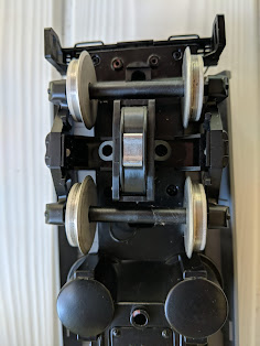
I took a prototyping circuit board I had and soldered on the capacitors and wires to the reset button and reed switches. A reminder, the reed switch detects when a magnet passes close by. I also added a few connectors for the wires going to the Arduino so I could remove them if needed in the future. The Arduino and circuit board are held in place with two-sided tape. For power, I took a barrel jack attachment and connected it to the wires coming from the small battery compartment. When I turn on the switch at the batteries, the Arduino powers up and the odometer is ready to run. The reed switch is mounted underneath next to a wheel with a magnet glued on. The reset button went under the coal load next to the display.
 |
| Display and reset button that hide under the coal load |
 |
| Circuit board with connections (in front) and Arduino (at back). |
I still needed to calibrate the distance as I was just guessing at the circumference of the wheels. I had an initial guess based on the wheel diameter but I wasn't sure where on the flange that was measured to and I know my mathematics don't always align with train reality. I was able to walk the coal tender along the straight segment of track a few times over a known distance and take the average. I needed a small adjustment but I think I am now correct to within one rotation of the wheel. That is the limit on the accuracy for using just one magnet on the wheel, since the sensor can only detect full rotations. If I want more accuracy, I will need to add more magnets around the edge of the wheel. But given how hard it was to get one magnet to stay still long enough to glue it, and how strongly these magnets attract each other, I can't imagine putting a second one on the same wheel. So I will live with a few inches uncertainty.
I also tested going around a full loop of the track and compared that against the distance as reported by track layout software, SCARM. Again, pretty close.
For the display, I settled on having the distance in actual feet (instead of scaled distances), the number of rotations/cycles, the actual distance in meters, and the average speed in feet per second. The first three are reset when the push button is pushed. For the speed, I start a clock with the first trigger of the reed switch. At each display update, the average speed is calculated (distance / time) and displayed. If the odometer goes longer than 1.5 sec without a reed switch trigger, I assume the train has stopped and the clock is paused until movement is detected again.
 |
| New four-line display. Note reset button at top. |
So that's it. My first working Arduino project for the train. It has sparked several other ideas so there should be more to come. While in the coal tender I replaced the old connector from the sound card and speaker with a new 8-pin connector. The speaker is connected and can be driven by the engine. I also connected the back-up light on the coal tender. I'm working on actually powering the odometer from the engine as well. More on that once it is finished.


Comments
Post a Comment